Technique solution
Customer: ****
Supplier: Ningbo Gongtie Smart Technology Co.,LTD.
Data No.: 2019*******
SOLUTION :
1. Products processing solution
1) customer: ****
2) product profile:
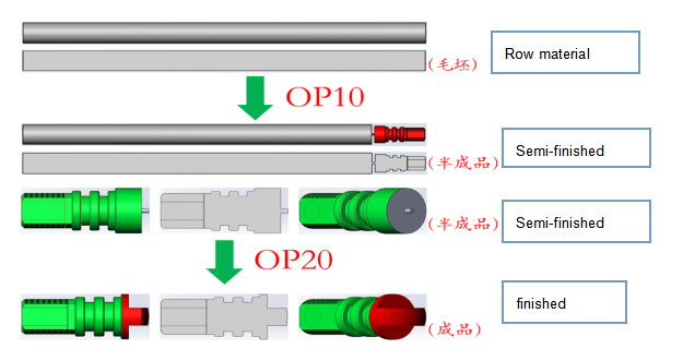
3) material: brass
4) machining accuracy: completely follow up the customer’s drawing;
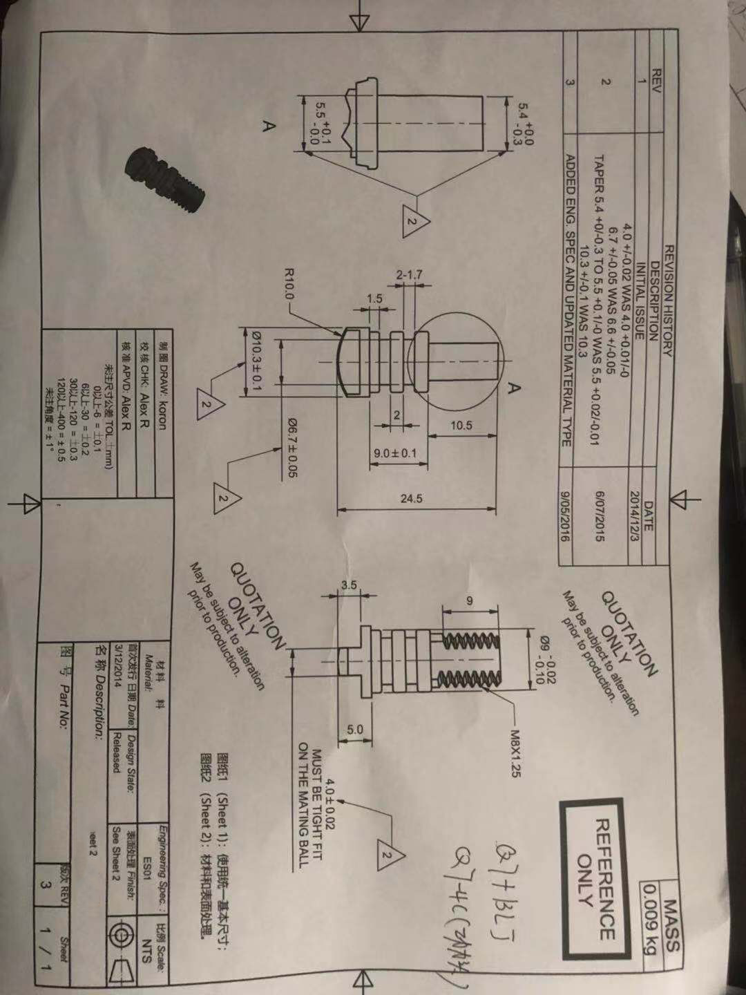
5) Work tool and fixture: OP10 and OP20 both will be machined with precise spring collet
6) The technique remarks: the program will set up the tools life-time management (customer pre-set up the q’ty of the machining products, when reach it, automatically warning, for reducing the products scraps and the tools damage.)
7) will be worked with additional live tool
the OP 10 clamping work piece draft | |||||
① Clamp from outside ② red area is the machining area | |||||
process | tools | Process speed(r/min) | Traverse (mm/r) | Cycle time(S) | Change-over time |
OD turning, face turning, chamfering | T1 OD knife
| 3000 | 0.09 | ≈10.0s | ≈1.0s |
Grooving |
T4 cutting groove knife
| 2400 | 0.07 | ≈8.0s | ≈0.5s |
Threading |
T2 thread knife
| 1500 | According to the thread | ≈8.0s | ≈0.5s |
Live tool for hexagon |
T3 live tool
| 1500/3000 | 0.06 | ≈9.0s | ≈1.0s |
Cutting |
T4 cutting groove knife
| 1800 | 0.05 | ≈4.5s | ≈0.5s |
Processing time | ≈43s | ||||
Bar feeder loading | ≈4.5s | ||||
Total | ≈47.5s | ||||
Remarks: due to no sampling, theoretically the processing time will have around 10% deviation. | |||||
| |||||
process | tools | Process speed(r/min) | Traverse (mm/r) | Cycle time(S) | Change-over time |
OD turning, face turning, chamfering | T1 OD knife | 3000 | 0.08 | ≈3.5s | ≈1.0s |
Live tool for hexagon and drilling hole |
T3 live tool | 1500/3000 | 0.06 | ≈7.0s | ≈1.0s |
Processing time | ≈12.5s | ||||
Robot hand loading/unloading time | ≈8.0s | ||||
Blowing time | ≈2.0s | ||||
Total | ≈22.5s | ||||
Remarks: due to no sampling, theoretically the processing time will have around 10% deviation. | |||||
5) Proposal equipment for OP 10:
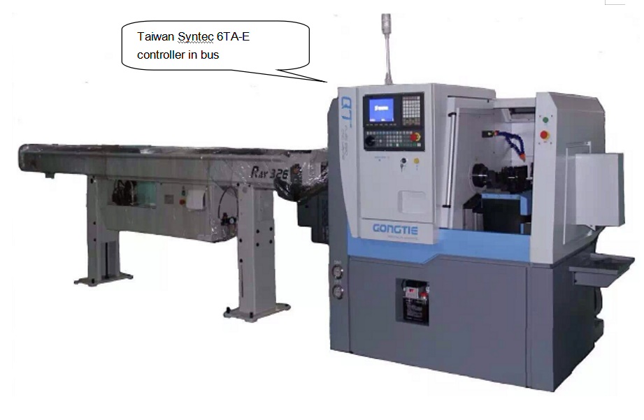
Precise linear guide-way CNC lathe with flat bed Q7 + bar feeder
6) CNC lathe sketch:
1> Precise linear guide-way CNC lathe with flat bed Q7
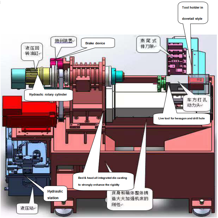
2> base bed:
3> bar feeder
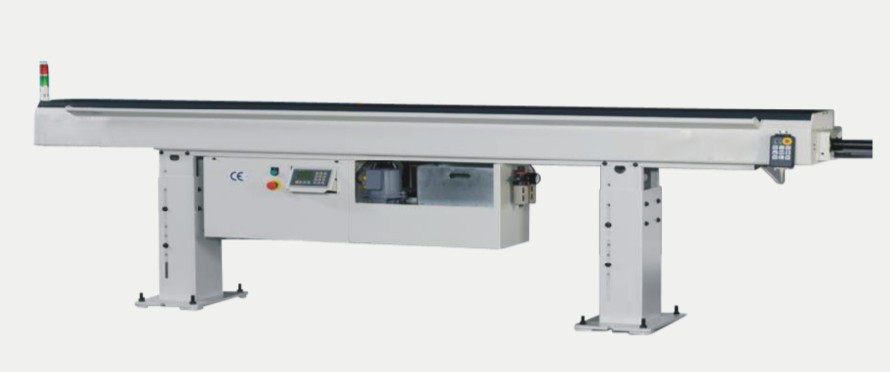
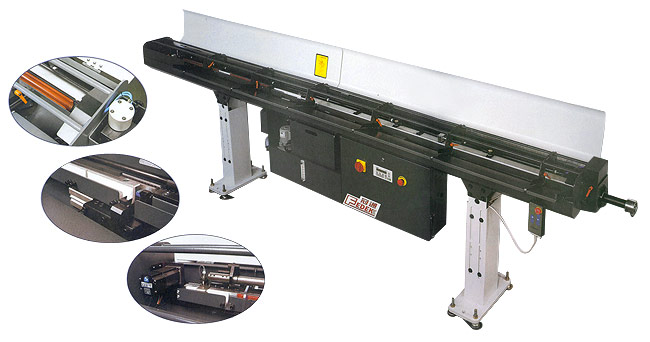
2. Parameters, configuration:
1) parameters:
Main parameters | UNIT | Q7 | |
Capability | Max. swing diameter | mm | 400/98 |
Max. turning length | mm | 300 | |
Max. bar through-hole | mm | 26(35) | |
Axis Stroke | X-axis travel | mm | 320 |
Z-axis travel | mm | 300 | |
Rapid Traverse | X/Z-axis | m/min | 20 |
Spindle | Spindle nose size | N/A | A2-5 |
Spindle hole through diameter | mm | 48 | |
Spindle servo motor power | kW | (asynchronous )3.7/5.5 | |
Spindle speed range | rpm | 0~5000 | |
The Min. traverse | mm | 0.001 | |
Hydraulic collet | N/A | 36 | |
Optional chuck | N/A | 6” | |
Toolholder | Number of tools | PCS | 5 |
Toolholder type | N/A | Dovetail row of knives | |
Toolholder center height in radial | mm | 50 | |
Tool size | mm | 16*16 | |
Accuracy | X\Z axis repeating postioning accuracy | mm | 0.002 |
Others | Cooling motor capacity | L | 120 |
Required electric power | kVA | 8 | |
Height from floor to spindle center | mm | ≈1070 | |
Overall size(L*W*H) | mm | 1700*1300*1650 | |
Net weight | kg | ≈1700 | |
2) Configuration and price
NO. | ITEM | COMPONENT BRAND & SPEC. | ORIGINAL COUNTRY | QTY. |
1 | Operation system | SYNTEC | TAIWAN | 1 |
2 | Servo motor/drive | SYNTEC | TAIWAN | 2 |
3 | Spindle motor | CTB/SYNTEC | BEIJING/ TAIWAN | 1 |
4 | Ball screw & linear guide-way | PMI | TAIWAN | 2,4 |
5 | Spindle bearings | NTN P4 | JAPAN | 5 |
6 | Spindle structure | Independent spindle with front three bearings and two after | BY GONGTIE | 1 |
7 | Ball screw supporting method | Double supporting with pre-stretching structure | BY GONGTIE | 1 |
8 | Hollow hydraulic rotary cylinder | 536 | TAIWAN COMPONENTS | 1 |
9 | Hydraulic system | SEVEN OCEAN | SHANGHAI | 1 |
10 | Electric cabinet with heat exchanger | NO. 5 | TAIWAN COMPONENTS | 1 |
11 | Low voltage component | SCHNEIDER | FRENCH | 1 |
12 | Hollow hydraulic collet | 36 | SHANGHAI | 1 |
13 | Tool-holder type | T-slot blade row | BY GONGTIE | 1 |
ADDED FACILITY | ||||
14 | Chips cleaner | Rear side | CHINA | 1 |
15 | Bar feeder | PG326(¢3¢26) | TAIWAN | 1 |
16 | Parts receiver | BY GONGTIE | 1 | |
17 | Live tool | Hexagon and drill hole | BY GONGTIE | 1 |
18 | Motor/driver | SYNTEC | TAIWAN | 1 |
7) Proposal equipment for OP 20:
Precise linear guide-way CNC lathe with flat bed Q7-4C or Q7C-4C with gantry loader in tray PLUS LIVE TOOL
8) CNC lathe sketch:
1> Precise linear guide-way CNC lathe with flat bed Q7-4C/ Q7C-4C
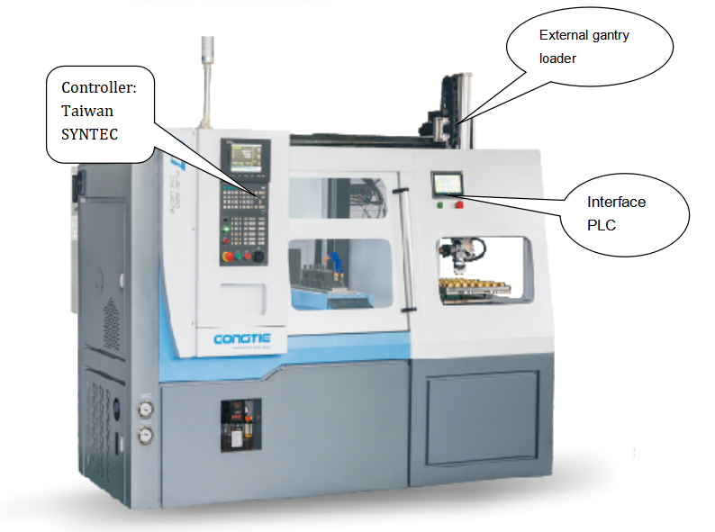
2> 2.1 ) the bed with feeding system in mechanical spindle:
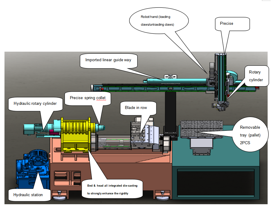
2.2 ) the bed with feeding system in motor spindle:
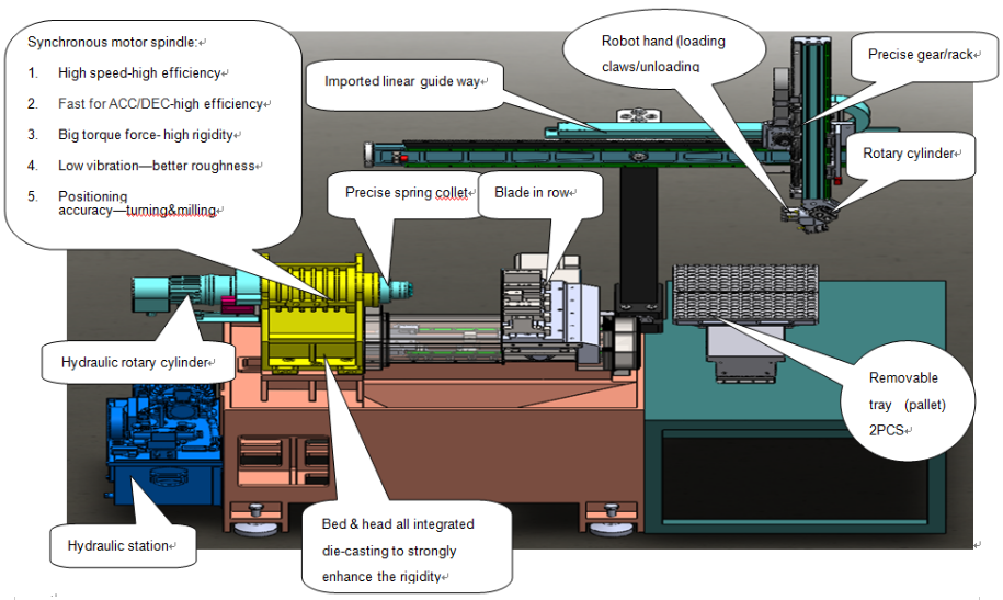
3> the robot hand and tray sketch for OP20:
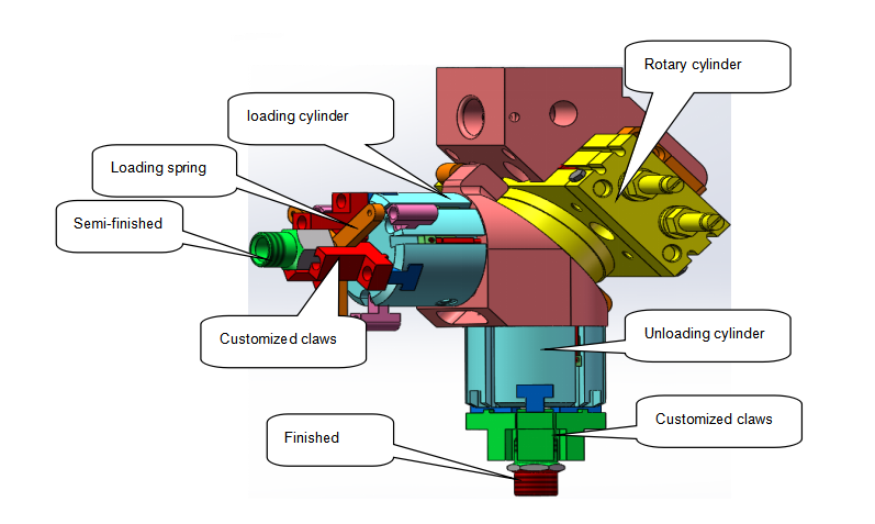
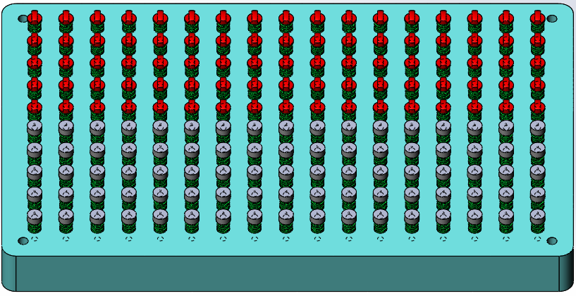
Remarks: the robot hand claws and tray layout is exactly based on customer’s products
4> the whole machine layout:
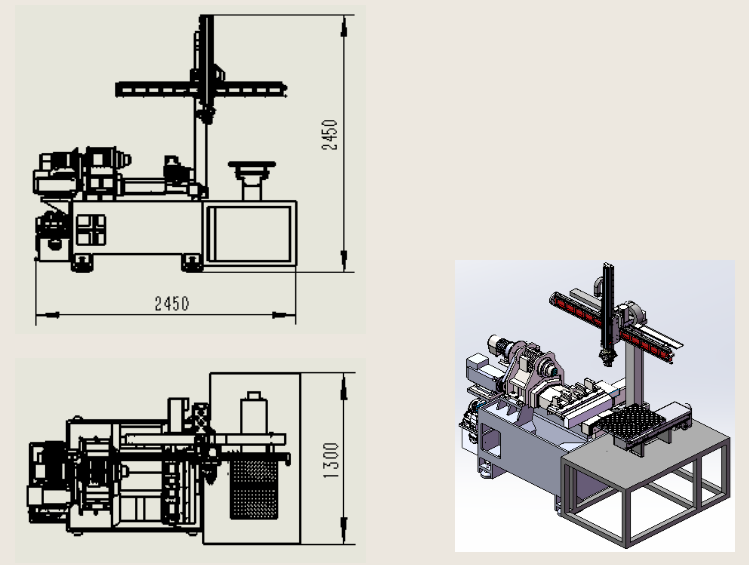
9. Parameters, configuration:
1) parameters:
Main parameters | UNIT | Q7 | |
Capability | Max. swing diameter | mm | 400/98 |
Max. turning length | mm | 300 | |
Max. bar through-hole | mm | 26(35) | |
Axis Stroke | X-axis travel | mm | 320 |
Z-axis travel | mm | 300 | |
Rapid Traverse | X/Z-axis | m/min | 20 |
Spindle | Spindle nose size | N/A | A2-5 |
Spindle hole through diameter | mm | 48 | |
Spindle servo motor power | kW | (asynchronous )3.7/5.5 | |
Spindle speed range | rpm | 0~5000/0-6000 | |
The Min. traverse | mm | 0.001 | |
Hydraulic collet | N/A | 36 | |
Optional chuck | N/A | 6” | |
Toolholder | Number of tools | PCS | 5 |
Toolholder type | N/A | Dovetail row of knives | |
Toolholder center height in radial | mm | 50 | |
Tool size | mm | 16*16 | |
Accuracy | X\Z axis repeating postioning accuracy | mm | 0.002 |
Others | Cooling motor capacity | L | 120 |
Required electric power | kVA | 8+4 | |
Height from floor to spindle center | mm | ≈1070 | |
Overall size(L*W*H) | mm | 2450*1300*2450 (including robot hand) | |
Net weight | kg | ≈2400 (including robot hand) | |
2) 3.1) Configuration with mechanical spindle:
NO. | ITEM | COMPONENT BRAND & SPEC. | ORIGINAL COUNTERY | QTY. |
1 | Operation system | SYNTEC | TAIWAN | 1 |
2 | Servo motor/drive | SYNTEC | TAIWAN | 2 |
3 | Spindle motor | CTB/SYNTEC | BEIJING/ TAIWAN | 1 |
4 | Ball screw & linear guide-way | PMI | TAIWAN | 2,4 |
5 | Spindle bearings | NTN P4 | JAPAN | 5 |
6 | Spindle structure | Independent spindle with front three bearings and two after | BY GONGTIE | 1 |
7 | Ball screw supporting method | Double supporting with pre-stretching structure | BY GONGTIE | 1 |
8 | Hollow hydraulic rotary cylinder | 536 | TAIWAN COMPONENTS | 1 |
9 | Hydraulic system | SEVEN OCEAN | SHANGHAI | 1 |
10 | Electric cabinet with heat exchanger | NO. 5 | TAIWAN COMPONENTS | 1 |
11 | Low voltage component | SCHNEIDER | FRENCH | 1 |
12 | Hollow hydraulic collet | 36 | SHANGHAI | 1 |
13 | Tool-holder type | T-slot blade row | BY GONGTIE | 1 |
ADDED FACILITY | ||||
14 | Chips cleaner | Rear side | CHINA | 1 |
15 | Live tool | CHINA | 1 | |
16 | Motor/driver | SYNTEC | TAIWAN | 1 |
17 | Brake device | CHINA | 1 | |
3.2) Configuration with synchronous motor spindle:
NO. | ITEM | COMPONENT BRAND & SPEC. | ORIGINAL COUNTRY | QTY. | ||
1 | Operation system | SYNTEC 22TA | TAIWAN | 1 | ||
2 | Servo motor/drive | SYNTEC 1.0W IN BUS | TAIWAN | 2 | ||
3 | Spindle motor | Synchronous motor spindle | ITALY | 1 | ||
4 | Ball screw & linear guide-way | PMI | TAIWAN | 2,4 | ||
5 | Spindle bearings | NTN P4 | JAPAN | 5 | ||
6 | Spindle structure | Independent spindle with front three bearings and two after | BY GONGTIE | 1 | ||
7 | Ball screw supporting method | Double supporting with pre-stretching structure | BY GONGTIE | 1 | ||
8 | Hollow hydraulic rotary cylinder | 536 | TAIWAN COMPONENTS | 1 | ||
9 | Hydraulic system | SEVEN OCEAN | SHANGHAI | 1 | ||
10 | Electric cabinet with heat exchanger | NO. 5 | TAIWAN COMPONENTS | 1 | ||
11 | Low voltage component | SCHNEIDER | FRENCH | 1 | ||
12 | Hollow hydraulic collet | 36 | SHANGHAI | 1 | ||
13 | Tool-holder type | T-slot blade row | BY GONGTIE | 1 | ||
ADDED FACILITY | ||||||
14 | Chips cleaner | Rear side | CHINA | 1 | ||
15 | Live tool | CHINA | 1 | |||
16 | Motor/driver | SYNTEC | TAIWAN | 1 | ||
17 | Brake device | CHINA | 1 | |||
Gantry loader feeding system configuration | ||||||
Auto-loading/unloading system | ||||||
No. | Kit | Brand & original country | QTY. | |||
1 | Beam kit | GONGTIE | 1 set | |||
2 | Beam linear guide-way | Taiwan PMI | 1set | |||
3 | Parallel hand | JAPAN SMC | 1set | |||
4 | Rotary cylinder | JAPAN SMC | 1set | |||
5 | Air cylinder | JAPAN SMC | 1set | |||
6 | Sensor/Magnetic switch | JAPAN SMC | 1set | |||
7 | Gear wheel/rack(slant gear) | Taiwan | 1set | |||
8 | Work-stocker system(in tray/pallet) | CHINA | 1set | |||
9 | Loading/unloading device(mechanical claws) | GONGTIE | 1set | |||
electrical system for gantry loader | ||||||
1 | Servo motor | Inovance-china | 1set | |||
2 | Servo system | Inovance-china(bus type CNC system) | 1set | |||
3 | Controller system | Inovance-china | 1set | |||
4 | Gear Reducer | Taiwan | 1set | |||
5 | interface | Inovance-china | 1set | |||
3. After-sales service
1) after assembly, immediately carry out test and try-run on the CNC lathe and gantry loader.
2) according to the problem feedback from customer by telephone or FAX, make the reaction within 12H.
3) conducting maintenance door to door, within 24H for Ningbo City, within 48H for zhejiang area, jiangsu area and shanghai. For the other areas, reaction time will be adjusted according to the actual condition.
4) In maintenance guarantee period (one year), if the damage is not caused by operators, we offer free maintenance service, beyond the period, we offer relevant services with paid components.
4. Attachments
Attached items | QTY |
Working instruction | 1 SET |
Machine guarantee card | 1 SET |
Electrics instruction | 1 SET |
Machine inspection report | 1 SET |
CNC system instruction | 1 SET |
Basic tools | 1 SET |
5. Lead time: 30 working time after signing contract
Copyright © Ningbo Gongtie Smart Technology Co., Ltd. All Rights Reserved | Sitemap Powered by 
